How does the software detect North direction?
- The North direction is taken based on the Sketchup’s cardinal direction.
- The Green line usually represents the North but it can be adjusted to simplify drawing.
- So Right click the Green axis line and check if the Reset option is enabled.
- If it is enabled then the Green line is different than the cardinal direction so Press Reset
- The following is true when the Axes are in the default position.
- Solid Green line is treated as North
- Dotted Green line is treated as South
- Solid Red line is treated as East
- Dotted Red line is treated as West
- Please refer to https://help.sketchup.com/en/sketchup/adjusting-drawing-axes for details.
How do I fix Group could not be loaded error?
- Check the Group names are correct.
- Check the Groups are not hidden on Outliner.
- Make sure the Groups exist according to the Analysis Type on Project Tab on Settings.
- Neighbour Analysis requires both Existing and Proposed groups.
- Proposed Scheme Analysis requires Proposed group.
- If the model consists of Proposed Scheme only, Change the Analysis Type to Proposed Scheme on Project Tab on Settings.
Can I run multiple calculations?
Yes. Open the calculation dialog. Select a test from the options and press Add to List. Repeat this for other calculations you want to run.
They will be grouped and sent to the service all together. Separate reports will be created for each unique calculation.
How can I change the height of the result texts?
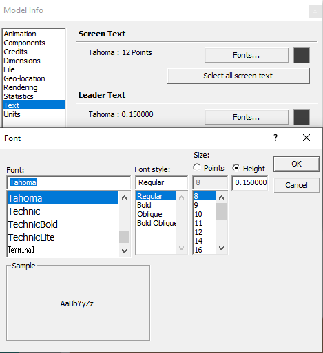
- Select “Window” then “Model info” from the menu then “Text”
- Finally click on Fonts Button on Leader Text Section
- The text scale better on the Size by Height option
- The results texts will change after the calculation is re-run
Why are the result texts coming too wide/far from?
- Open Settings dialog
- Go to Settings dialogue -> Application Settings -> Calculation.
- Change Text Offset value from the Text Offset option.
The value should be entered in meters regardless of the unit used in the model.
The contour image does not look correct or match the texture image
If the contour image does not match the texture image from the model:
- Face style must be Shaded With Textures.
- Go to View Menu on Sketchup Menubar then Click on Face Style and Select Shaded With Textures.
How can I change the criteria for different assessments?
- To set the criteria for VSC, APSH and Amenity, Open the settings dialogue > Project Settings > Assessment Criteria.
- DD criteria cannot be changed.
Can I move the VSC/APSH test sensor location?
- Open the Register dialogue -> Window.
- Go to Offsets section and set offset values.
- The offset values will be applied in the direction of the face orientation.
Why do all the traffic light icons look same color after running calculations?
- The “Color by layer” may have been ticked.
- Untick the option on Layers Tray then Details (Small arrow on the right side of the tray)
How can I set room types for DD and ADF calculations?
- The room type used for ADF or DD calculation is either taken from the room layer name or the “Room Type” selected during registration of room from registration dialog.
The room type from the layer name is used if defined otherwise the value from the room type list is used.
To set room type by layer: The layer name must be in a specific format : LayerName_$RoomType_$ReqValue e.g. LayerName_$Bedroom_$1.5
You can use the room type dialogue to create all the required layers in correct format. For this follow the following procedure:- Step 1: Open the registration dialogue.
- Step 2: Go to room tab.
- Step 3: Click on the “
 ” icon next to Room Type option, the room type dialogue will appear.
 - Step 4: Tick the room types that you want to create the template layers for them and click on “Create Layers” button to create layer in the expected format.
In-order to update/change the “Room Type”:
- Step 1: Open the registration dialogue.
- Step 2: Go to room tab and select Update option.
- Step 3: Query and select the rooms you want to update from entity info table. (Ctrl + click or tick on box for multiple selection.)
- Step 4: Select the desired Room Type from the dropdown list in Space Type section.
- Step 5: Finally, click on Update button to execute update room type command.
How do I change the density of the sensor points on DD calculation?
To change the Grid Spacing follow the following procedure:
- Step 1: Open register dialog from Menu.
- Step 2: Navigate to Room tab.
- Step 3: Go to Working Plane & Grid Spacing section.
- Step 4: There you will find Grid Spacing textbox.
Can I change the DD/NSL result image colors ?
Yes.
The colors can be changed in the Legend Settings.
Where can I set Glazing Transmittance for ADF test?
To set the Glazing Transmittance for ADF test follow the following steps:
- Step 1: Open the Register dialog from menu.
- Step 2: Navigate to Window tab within register dialog.
- Step 3: Go to Glazing section.
- Step 4: There you will find Transmittance option, update the value.
All other ADF parameters must be updated from Settings. For this:
- Open Setting Dialog.
- Switch to Application Settings.
- And Go to Room Properties.
What do the DD/NSL result image colours represent?
- Existing/Proposed Contour
- The legend color image is saved as DD_.png file on Images/RoomLegend folder in the job folder.
- Ratio Contour
- The legend color image is saved as DD_Ratio.png file on Images/RoomLegend folder in the job folder.
Is it possible to change the DD threshold factor to match the ROL analysis criterion?
No. Although same sky type and methodology is used on calculating NSL test, the threshold cannot be changed for DD to match the ROL test.
What do the Amenity result image colours represent?
Legend values set in the Legend Settings for Amenity are used on the contour images.
- Existing/Proposed Contour
- The legend color image is saved as AMENITY_.png file on Images/RoomLegend folder in the job folder.
- Ratio Contour
- The legend color image is saved as AMENITY_Ratio.png file on Images/RoomLegend folder in the job folder.
Where can I set a different location for Amenity or APSH test?
To set different location for Amenity/APSH test follow the following steps:
- Step 1: Open the Settings dialog from Menu.
- Step 2: Navigate to Project Setting. (By default you will be in Project setting Section. Make sure that the Project Settings tab on top is highlighted in white color.)
- Step 3: Click on general tab. (By default general tab is opened. Make sure that the general tab is highlighted with blue text.)
- Step 4: Adjust the Climate file location settings accordingly.
Note: Make sure to untick “Use BRE location data for APSH/Amenity calculations”.
You can add new climate data file by placing the weather file in below folder:
%appdata%\MBS Software\DaylightForSketchup\Climate Files