How to name the group?
- Groups must be named precisely. EXISTING, PROPOSED and SURROUNDING
- EXISTING: For buildings/structures which are to be demolished.
- PROPOSED: For buildings/structures which are to be added.
- SURROUNDING: For buildings/structures which stay the same.
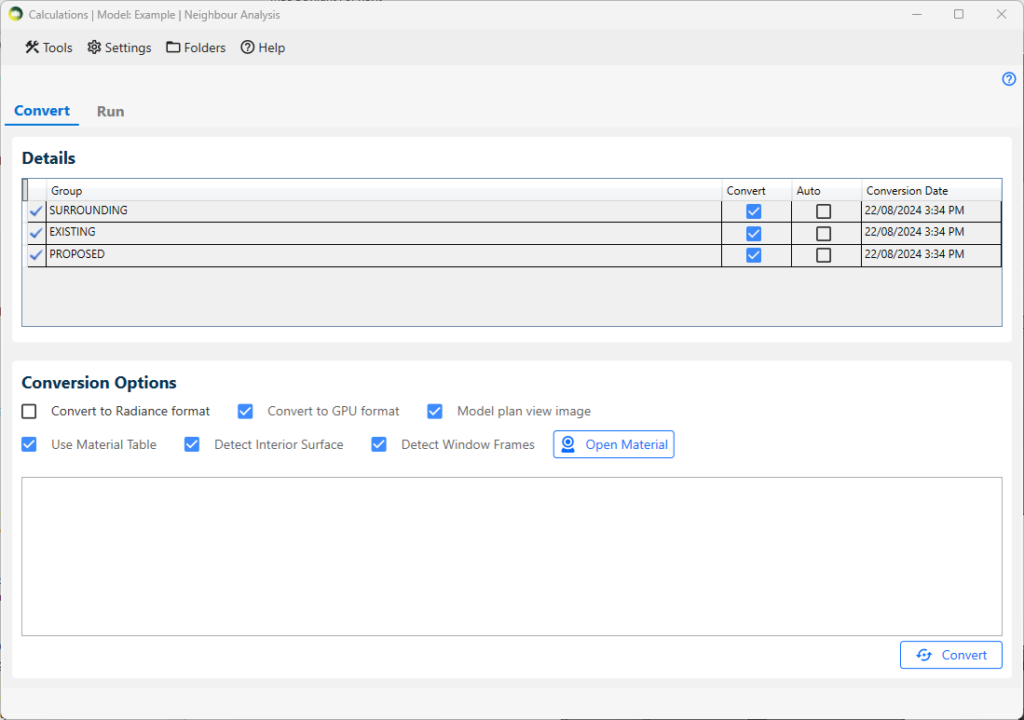
What are the steps to convert the model?
- In the Details section, select the convert checkbox next to the group in which you are interested.
- In the Conversion Options section:
- If you want to run calculations in GPU, tick on the Convert to GPU format option. It requires a compatible graphics card.
- If you want to run DF and Climate calculations in CPU, the Convert to Radiance format option must be ticked. ROL and BRE calculations on the CPU don’t require Radiance conversion.
- Tick the Use Material Table option to use a material table.
- To modify the material table, please click on Open Material button. For more details on the material settings, please refer to Material Knowledge Base.
- Click on the Convert button located at the right-bottom corner of the dialogue.
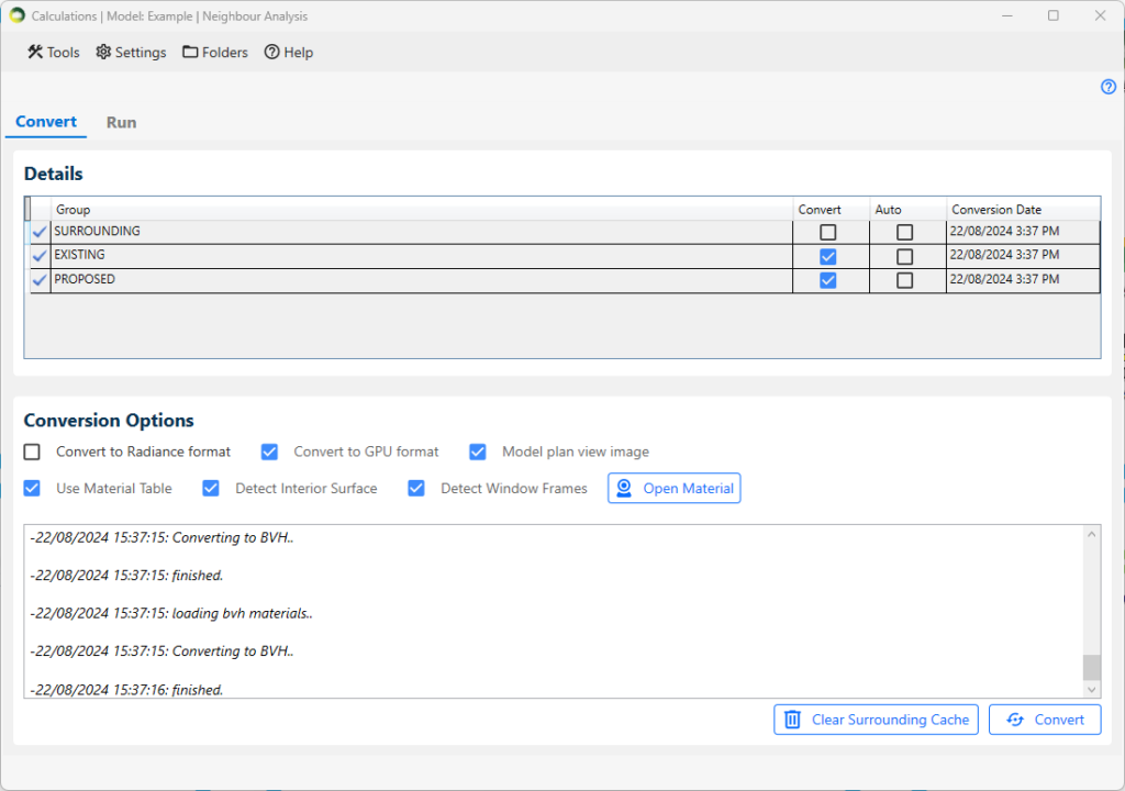
How to avoid re-converting a large surrounding every time?
- The convert option for the Surrounding group must be unticked and the Existing and Proposed group should be ticked before conversion.
- A cache file will be created on the first conversion for surrounding and any subsequent conversion will re-use that.
- If the surrounding group changes, then the cache must be cleared with the Clear Surrounding Cache button and Convert again
Can registered windows be added to any groups?
- Registered windows should be in either the Proposed or Surrounding group based on where they are.
- The same window must not be added to both the Proposed and surrounding group.
Can the conversion automatically detect interior floor, wall and ceiling surfaces?
If you tick Detect Interior Surface and Detect window Frames options, detect interior floor, wall and ceiling surfaces will be detected based on the Revit room and wall orientation and grouped together as below so materials can be applied easily.
- mbs_floors
- mbs_interiorwalls
- mbs_ceilings
- mbs_windowframe
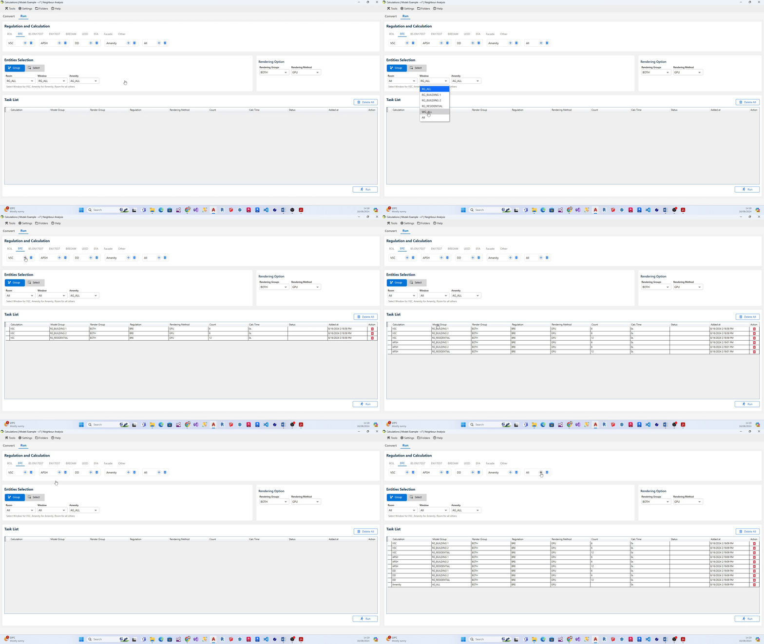
What are the steps to add calculations to the list?
- Select the relevant regulation (eg: ROL, BRE, BS EN17037). The associated calculations get displayed below each regulation.
- Set the Group on the relevant boxes.
- Click on the + icon next to the calculation name to add the individual calculation.
- Alternatively, Click on the + icon next to All to add all the calculations in the regulation.

What are the steps to add multiple groups for a calculation to the list?
- Select the relevant regulation (eg: ROL, BRE, BS EN17037). The associated calculations get displayed below each regulation.
- On Enitities Selection section, Select All option from the relevant entity (i.e. Room, Window, Amenity, Facade). Note: All option will be displayed only if there is more than one group in that particular entity type.
- After selecting the All option, click on + icon next to the desired calculation. Alternatively, you can click + icon next to All calculations if you would like to add all the groups for the calculations in the regulation to the task list.
What are the steps to modify group for calculation on the list?
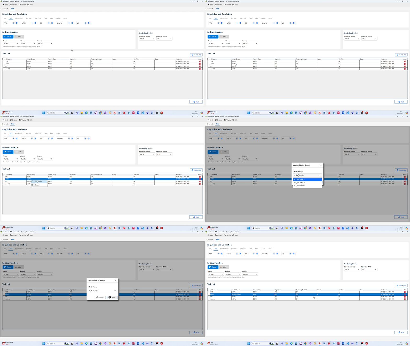
- Head to the relevant task on the task list and right-click on it.
- A little popout dialogue containing the list of relevant groups for the selected calculation will appear on your screen.
- Select the required group and click on Save.
What unit is used by the software?
- Meters.
- The model will be automatically converted to meters during conversion/registration stage regardless of the unit used by Revit model.
Why are the graphical results not visible in the model?
- The room results can be shown in two different ways.
- First option is based on the Autodesk® Revit Analysis Visualization Framework.
- The second option is based on an image placed on a generic model object.
- The option can be set in Application settings Calculation tab. Second option is set by default.
- The result images created using the first option are temporary and are deleted when the model is closed. The graphical results are only visible in Shaded or Hidden line Visual Style. Load Result option can be used to recreate the result images.
- The result images created using the second option are permanent and are saved with the model. The graphical results are only visible in Realistic Visual Style. Load Result option can be used to recreate the result images.
- If the results are partially visible, check to make sure Color Fill is not blocking the results. Go to Visibility/Graphics – Rooms and Untick the Color Fill option

How is the target area calculated for room point based calculations, from the graphical result?
The target area (as in the exported report) for Daylight Distribution, Daylight Factor and Climate based calculations might not tally up exactly with the graphical results visible in the model.
This is due to the fact that the Waldram Tools software uses Autodesk® Revit Analysis Visualization Framework to represent the graphical result on surfaces while the calculations are done in MBS.
The target area for
- Daylight Factor and Climate based is simply calculated by (equally weighted) averaging the calculation points result within the room area.
- Daylight Distribution (No Sky Line) the contour is interpolated from the points result (in the same way as in Waldram Tools AutoCAD package).
How is the window frame affecting the calculations?
- It would not affect calculations, such as VSC, where the sensor is located on the outer face of the window.
- The frame if present blocks the view and daylight for all the room point based calculations such as Daylight Distribution, Daylight Factor and Climate Daylight.
- For ADF where the calculation point is behind the glazing by a small offset the frames do not take part in calculating the Sky Component (and to eventually derive the theta angle) as there is a chance that the sensor gets blocked by part of the frame. The frame factor therefore is set to 1 automatically for registered windows. And (to compensate) the glazed area is exactly calculated as the sum of all the glazing elements in the window.
What transparency value should be used for Waldram image?
- If the Waldram image based calculation (VSC, APSH, ADF) is run for Neighbour analysis, the image will combine Existing and Proposed images onto a single image.
- The transparency of the image can be set in Application Settings > Colours tab.
- Transparency :155 (or anything in middle) = Both visible
- Transparency: 0 = When overlapping, Proposed on top, Existing Hidden
- Transparency: 255 = When overlapping, Existing on top, Proposed Hidden
What does the colour of the dot indicate in APSH Waldram diagram?
- Dark Blue dot indicates Winter sun
- Dark Yellow dot indicates Summer sun
- light Blue dot indicates blocked Winter sun
- light yellow dot indicates blocked Summer sun
- Dot with a hole indicates that the dot is seen by more than one window in the same room.
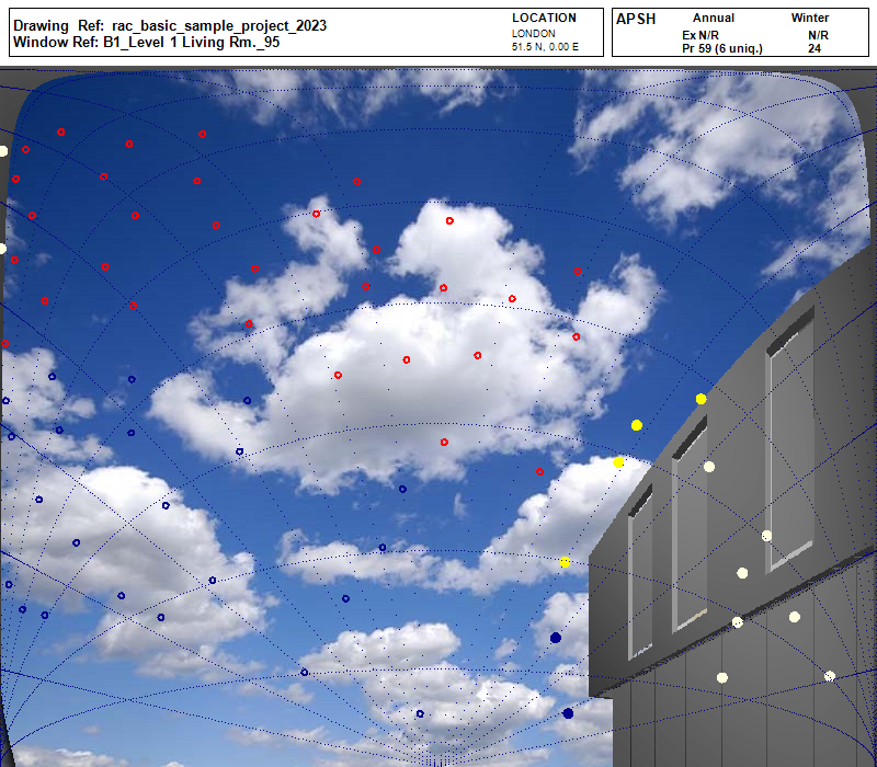
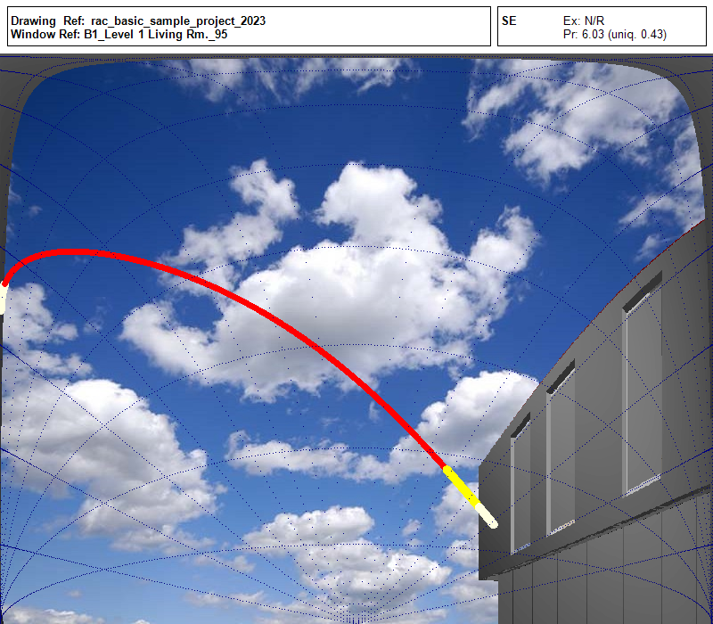
What does the colour of the dots indicate in SE Waldram diagram?
- Dark Yellow dot indicates the sun dot visible from the window.
- Light yellow dot indicates the sun dot blocked for the window.
- Red dot indicates that the dot is also seen by more than one window in the same room.