How to activate the Trial License?

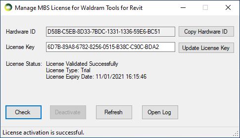
The Trial license is automatically activated when any of the MBS dialog is open for the first time.

  • The license will be valid for 7 days from the time of activation and gives access to Full features of the Plugin.

To Check the status of the Trial License

  • Click Utility Tools on MBS toolbar then click Manage License
  • Press Check

How to upgrade to the Subscription License?

  • Once you purchase a Subscription license from MBS, We will provide you with a Subscription version License key.
  • Click Utility Tools on MBS toolbar then click Manage License.
  • Paste the new key to the License Key textbox and Press Update.
  •  Press Activate. (Internet connection is required).
  • The software validates the license regularly with our license server to allow the license to be used on multiple computers.
  • Sometimes firewall or anti-virus restrictions can block the license activation and validation. Contact us for details about the license server address which the IT team might need in order to allow the activation.

* The plugin can be installed and used on multiple computers. There is a 30 min cooling off period once the plugin is used on one computer before it can be used on another computer.

How to transfer license to another computer?

  • The plugin can be installed and used on multiple computers.
  • There is a 30 min cooling off period once the plugin is used on one computer before it can be used on another computer.
  • If the plugin needs to be used before the cooling off period, the license needs to be de-activated from the computer where it was last used.
  • Click Utility Tools on MBS toolbar then click Manage License
  • Press Deactivate
  • Once it is de-activated, it can be used on another computer.

What are the steps to create Groups?

  • Groups can be created by selecting from pre-populated common ones from the Type combo box or by selecting New Group, New Room Group, New Window Group option.
    • Once the name is selected or input on the Name text box, Create button should be pressed which offers to select items to be added to the new group.
    • Room or Window group automatically filters only room/window when adding items.
    • Any  item under a category which is ticked on the exclude list is ignored when selecting items to be added to the group.
      • Some categories such as Plumbing and Furniture are always excluded from the groups by default.
      • If those items need to be added to a group, they can be unticked from the exclude list temporarily.

What are the steps to Update Groups?

  • Remove items under certain category
    • Tick the categories on the exclude list and then Select the Group name and then Update button.
    • Any items under newly ticked categories will be removed from the group.
  • Remove items by selecting them
    • In order to remove items, press Remove button and then select the items to be removed from the group.
    • In order to remove items by selection, the category which a item belongs to must not be ticked on the exclude list.
  • Add new items to the group
    • To add items by selection: Press Add button and select elements from the model to be added to the group.
    • In order to add items under a category: Untick the category on the exclude list first, and then press Add button to select elements.
      (unticking a category from the filter list would not automatically add category elements to the group.)

How to exclude objects from Revit Links?

  • Revit Links are inserted as single object to the group so it is not possible to exclude objects when adding them to the group.
  • Objects from all phases are included and is not possible to filter by phase.
  • They are filtered at the conversion time based on the exclusion list.
  • Tick the categories on the exclude list and then close the group dialogue. The list is saved on Project settings and will be used on conversion time.

How to exclude objects from Imported Autocad DWG instances?

  • Autocad DWG Links are inserted as single object to the group so it is not possible to exclude objects when adding them to the group.
  • However it is possible to exclude objects by layer from the import instance itself.
  • Select the imported dwg instance and then Click Modify and the Delete Layers. Select the layers to exclude and Press Ok.
  • Refer to Revit help topic “Delete Layers in CAD files” for step by step guide.

Which groups should the windows be on?

  • Windows must be added to the group where they exist.
    • Windows on Proposed buildings should be added to Proposed group.
    • Windows on Surrounding building should be added to Surrounding group.
    • Any windows on Existing buildings should be added to Existing group.
  • If Windows are registered after the model is converted, the model must be converted again to make sure the calculation process includes the windows correctly.
  • The results will be incorrect if the registered Windows are not added to the relevant groups.

What are the steps to register Revit windows?

  • Standard Revit windows and doors and curtain panels with glazing can be registered as windows.
  • Open Register Dialog and go to Register Mode then Window tab.
  • Detect All Levels button shows all the windows which can be registered. Users can also pick windows to register by using Select Manually button. Any windows which are already registered will not show up here.
  • Register Windows button registers the windows which are selected on the data grid.
  • Window Id
    • Building Name is read from the Building combo box.
    • Floor name is read from the Revit Level where the window is placed. If Revit Level is not defined then the centre of the window is used to detect the correct level name.
    • Window name is read from the Revit Paramter ‘Mark‘. If the Mark is empty, UnNamed will be used with a counter.
  • Window Normal
    • The normal is decided by intersecting with room or floor in the direction of window facing orientation then on the opposite direction. It handles the situation when window/wall flipped are incorrectly.  If there is no room and floor then window’s facing orientation will be used.
  • Shared parameters
    • Some of the window properties are added as shared parameters in the model and they can be updated via Window tags or schedule.
    • Building name, description, property type, glazing transmittance, adf, vsc and apsh offset values can be updated.

What are the steps to register Revit Rooms?

  • Standard Revit Rooms which are placed in the model and are correctly bounded by walls can be registered as rooms.
  • Open Register Dialog and go to Register Mode then Room tab.
  • Detect All Levels button shows all the rooms which can be registered. Users can also pick rooms to register by using Select Manually button. Any rooms which are already registered will not show up here.
  • Register Rooms button registers the rooms which are selected on the data grid.
  • Room Id
    • Building Name is read from the Building combo box.
    • Floor name is read from the Revit Level where the room is placed.
    • Room name is read from the Revit Paramter ‘Number‘. If Number is empty, UnNamed will be used with a counter.
    • Room type is read from the Revit Paramter ‘Name’. If the Name is empty, Undefined will be used.
  • Ceiling Height is set at time of registration based on ray intersection of the nearest ceiling or roof. If this method fails then value defined in the register dialog is used. It can be changed later by simply modifying the shared parameter property MBS_CeilingHeight  on revit room.
  • Shared parameters
    • Some of the room properties are added as shared parameters in the model and they can be updated via Room tags or schedule.
    • Building name, description, property type, required adf value, adf reflectance values, ceiling height and grid spacing can be updated.

How to specify offset values for VSC, APSH and ADF?

  • The reference calculation point is on the Outside face of the wall for windows hosted on the wall and on the glazing itself for the curtain and door panels.
  • Offset value should be positive to go towards the room and negative to go away from the room
  • The VSC and APSH offset values are read from the textboxes but ADF offset value is set based on the type of the window and/or its host as below. The offset can be updated later on the Update mode.
Window Type ADF Offset
Windows hosted on Wall/Roof Half of the Wall/Roof width
Curtain or Door Panels 0

Can room/window groups be automaticaly created?

  • Yes. Register dialog/Create Groups

What unit is used by the software?

  • Meters. If the model is in millimeters, Registration and conversion process would take forever and/or give error. Model must be scaled to meters.

Why are the graphical results not saved in the model?

Room point based calculation results such as Daylight Distribution, Daylight Factor and Climate Daylight, are graphics and NOT residents of the database – so they don’t add to the size of the Revit
model and they don’t persist.

If you want them again later you need to rerun the calculation or load back the saved results using Load Results dialogue.

Why are the graphical results not visible in the model?

  • The graphical results are not visible in Wireframe visual style. So change the style to Shaded or Hidden line.
  • If  the results are partially visible, check to make sure Color Fill is not blocking the results. Go to Visibility/Graphics – Rooms and Untick the Color Fill option

How is the target area calculated for room point based calculations, from the graphical result?

The target area(as in the exported report) for Daylight Distribution, Daylight Factor and Climate based calculations might not tally up exactly with the graphical results visible in the model.

This is due to the fact that the Waldram Tools software uses Autodesk® Revit Analysis Visualization Framework to represent the graphical result on surfaces while the calculations are done in MBS.

The target area for

  • Daylight Factor and Climate based is simply calculated by (equally weighted)averaging the calculation points result within the room area.
  • Daylight Distribution(No Sky Line) the contour is interpolated from the points result(in the same way as in Waldram AutoCAD package).

How is the window frame affecting the calculations?

  • It would not affect calculations, such as VSC, where the sensor is located on the outer face of the window.
  • The frame if presents blocks the view and daylight for all room point based calculations such as Daylight Distribution, Daylight Factor and Climate Daylight.
  • For ADF where the calculation point is behind the glazing by a small offset the frames do not take part in calculating the Sky Component(and to eventually derive the theta angle) as there is a chance that the sensor gets blocked
    by part of the frame. The frame factor therefore is set to 1 automatically for registered windows. And (to compensate) the glazed area is exactly calculated as the sum of all the glazing elements in the window.

What transparency value should be used for Waldram image?

  • Transparency: 0 = When overlapping, Proposed on top, Existing Hidden
  • Transparency: 255 = When overlapping, Existing on top, Proposed Hidden
  • Transparency :155 (or anything in middle) = Both visible

What does the color of the dot indicate in APSH Waldram diagram?

  • Dark Blue dot indicates winter sun
  • Dark Yellow dot indicates summer sun
  • light Blue dot indicates blocked winter sun
  • light yellow dot indicates blocked summer sun
  • Dot with hole indicate that the dot is seen by more than one window.

What does the colour of the dots indicate in SE Waldram diagram?

  • Dark Yellow dot indicates sun dot visible from the window.
  • Light yellow dot indicates sun dot blocked for the window.
  • Red dot indicates that the dot is seen by more than one window in the room.

What are the steps to Preview the results?

  • Select the required tab Window(s)/Room(s)/Amenity
  • Tick Self Test option if the result is only for Proposed group
  • Use a Group or Select items on combo box below the calculation name
  • VSC and APSH results are shown together and uses VSC group
  • Click Preview
  • Note: There is no need select the tick boxes next to the calculation name for Preview

What are the steps to Export the results?

  • Select the tick boxes next to the calculation name to be exported. (ROL, DD, ADF, VSC, APSH, Amenity or ALL)
  • Tick Self Test option if the result is only for Proposed group
  • Tick CSV Report option to export the results in csv format
  • Use a Group or Select items on combo box below the calculation name
  • VSC and APSH results are exported in same sheet for (default) report and uses VSC group. Bespoke reports may vary.
  • Click Export to File

How to use tags from Project Settings in Reports?

  • Replaceable tags can be inserted in Excel template including header and footer. They should be specified as <tag> e.g. <Project Name> <Report Title>. The values can be defined in Project Settings dialog.

What are the steps to add results to the label?

  • Select entity type Window/Room
  • Tick Existing, Proposed or both options as necessary
  • Select the result to be added VSC/APSH/ADF/DD
  • Tick Add to Active View option to place the tags on the current view. They are added to the plan view which correspond to the Level where the host Window/Room is placed.
  • Click on Add Labels to add/update labels
  • Modified version of Revit room tag is used as room label and shows Room number, name (used as room type), required adf and result labels.
  • Modified version of Revit window, curtain panel and door tag is used as window label and shows Window mark, glazing transmittance and result labels.

How can I change the size of Room and Window tags?

  • Right click the tag which needs to be resized and Click Edit Family.
  • Select the label and Click Edit Type on the Properties Panel
  • Change the Text Size as necessary
  • Press Load into Project and Close
  • Press Yes to Save changes to the tag
  • Press Override the existing version and its parameter values

What are the steps to add results as Solids?

  • Select entity type Window/Room
  • Tick Existing, Proposed or both options as necessary
  • Select the result to be added VSC/APSH/ADF/DD
  • Click on Add Solids to add/update solids.
  • Both window and room results are added to the default 3D view as a window face with colours for pass, fail and nearly pass.
  • The colours are best seen on Shaded mode.
  • No solids will be added if the calculations have not been run.

Window orientation and Calculation Points

  • Window Orientation
    • Displays a line showing the window orientation detected.
    • Incorrect orientation detection causes wrong results.
  • Calculation Points
    • VSC, APSH and ADF calculation points can be shown
    • A point offset (based on registered offset values) from the centre of the window face in the direction of orientation is drawn.

Filter Results

  • Analysis Results
    • Contour results can be filtered for calculations  DD and DF
    • They appear on plan view respective to the level where the rooms exists.
  • Solids
    • Solids results added from Label dialog can be filtered for calculations such as VSC, APSH, DD and DF
    • They appear on the default 3D view on Shaded mode.

Window face and ADF glazing faces

  • Window face
    • This command can be used to check the face whose centre is used as calculation point for VSC and APSH and ADF calculations.
  • Window ADF Glazing Faces
    • This command can be used to check the glazing faces used for glazed area of ADF calculations.
  • The faces are added to the default 3D view.
  • Remember to delete them when not needed using Delete Inserted Faces option.

What are the steps to register a facade and run the facade analysis?

  • Select the faces to run the facade analysis and then press Register Facades
  • They will appear as a group for calculations such as VSC and APSH.
  • Run the calculation for the selected facade group.
  • The facade face will show the results colors based on the color mode options in Settings-Legend.
  • Results can be filtered using Filter Results commands and then Analysis Results

How can I get the facade results when I reopen the model?

  • The facade results are stored as Analysis results in Revit and are not saved after the Revit session closes.
  • They can be saved as an Image. Right click the view and Save to Project as Image. The image will be saved under Views-Renderings.
  • The full results can also be loaded to the view by going to Calculation dialogue – Tools- Load Results and then selecting the .Out file for the facade result.

How can I assign materials to surfaces for ray tracing calculations?

Material Dialogue is possibly the easiest way to assign material to surfaces.  Tick the Use Material Table option.

The materials are read from Revit faces during the first conversion. The values can be overridden in the table if necessary.

The indoor surfaces, ceiling and floors of all Revit Rooms (either MBS registered or not) can be detected. Tick the Detect Interior Surfaces option.

If this option is not ticked, the material is read as it is set the Revit Faces. If the option is ticked the table will add three entries for the wall, floor and ceiling with default value of 0.5 reflectance.

“MBS_InteriorWalls”, “MBS_Floors”, “MBS_Ceilings”

Another way to apply material is to select Revit elements and use Revit Paint tool to directly apply material to the face of the element. This way no material assignment is required through the Waldram Tools Material Dialogue.

RevitMBSMaterial

Why am I getting "Cannot modify group" errors?

  • The Revit model groups don’t like if object within a group is modified without entering the Edit group mode. And Revit API doesn’t provide simple option to edit groups in order to modify objects.
  • It is highly recommended to avoid putting Windows and Rooms in such groups to avoid errors.

Why are Rooms not visible in the Plan View?

  • Visibility/Graphics Override for the Plan view must have Rooms-Reference option ticked for being visible.

Why doesn’t the select tool pick a room in the plan view?

  • Select element by face option must be un-ticked in the Select option for the Modify for the room selection to work.

Why is the Room separator ignored when trying to modify room shape?

  • The room separator must be added to the plan view where room was created.
  • Check the Level for the room and open the plan view respective for that Level.