Transient Shadow Analysis
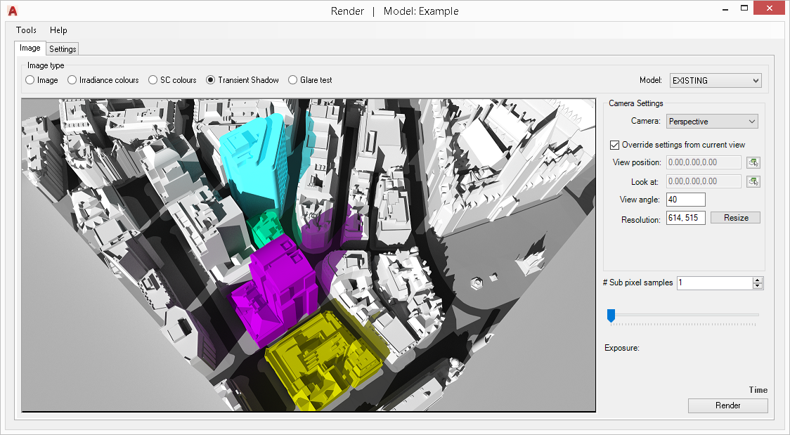
Objects in Proposed and Existing group would cast shadows same colour as their material colour. Transient Shadow Test image can be rendered using CPU or the GPU.
- Open the Application Settings > Calculation tab and choose the desired Rendering method. (GPU render require a compatible NVIDIA graphics card)
- Specify location by selecting the corresponding climate file location in Project Settings > General tab
- Open the Render dialog options > Transient Shadow tab and set the required test start and end time.
- Set the required interval (in minutes).
- The individual equinox dates can be easily set by selecting the desired date from the combo box.
- The Run All Dates option can be ticked to run for three dates 21 March, 21 June and 21 December in one Render. The times are in GMT.
- In Image tab select Shadow Test and pick the model group from the box.
- Set Camera mode to Perspective.
- Camera position and look At can be set in two ways: A. Either tick the “Override settings from current view” to setup the camera to the current view or a predefined camera. This option works better in AutoCAD Perspective mode. B. Press the View Position box button to select the position from the model. Repeat the process for Look At.
- Horizontal field of view is set via View Angle box. The effect is similar to zoom in or out.
- The image box can be resized manually through resizing the dialogue or by setting the desired resolution in Resolution box and pressing the resize button.
The resolution can also be manually be set to a value bigger than the display screen. - Set pixel samples number and press Render. The noise is inversely proportional to square root of this number: four times more samples are required to decrease the error by half.
- The shadow images are saved in the [Model_Name]_Waldram/Images/ShadowTest folder. Image file name will include the day, month and the time. No image is created for the times where the sun is not present e.g. after the sunset.

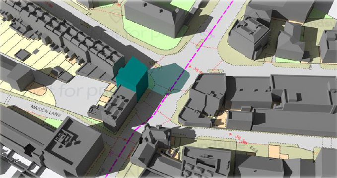
A background texture image can be set by inserting a Raster image into the model. Make sure the image belongs to either of the analysis groups.
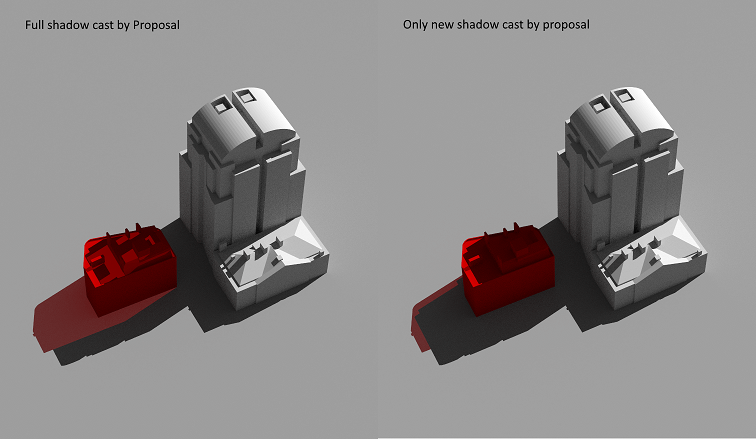
Tick the New Shadow Only option to exclude part of the coloured shadow that already is rendered under the existing scenario.
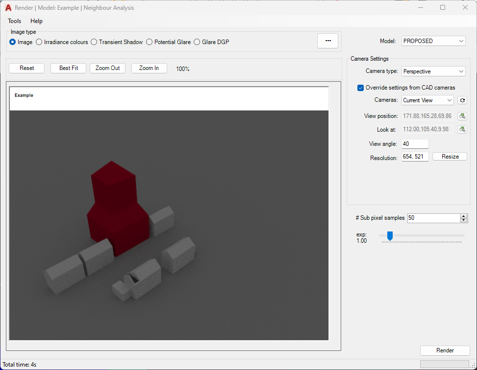
Normal Image
- Open the Render dialogue
- Specify location by selecting the corresponding climate file in Project Settings > General tab.
- Pick Radiance or PathTracing from the Render dialog options > General tab > Raytracing Method combo box.
- Also Set sky type, date and time on the same tab.
-
Select Existing or Proposed model from the Model box.
-
Camera position and look At can be set in two ways: A. Either tick the Override settings from current view to setup the camera to AutoCAD current view. This option works better in AutoCAD Perspective mode. B. Or press the View Position box button to select the position from the model. Repeat the process for Look At.
-
Horizontal field of view is set via View Angle box. The effect is similar to zoom in or out
- The image box can be resized manually through resizing the dialogue or by setting the desired resolution in Resolution box and pressing the resize button. The resolution can also be manually be set to a value bigger than the display screen.
- Set pixel samples number and press Render. The noise is inversely proportional to square root of this number: four times more samples are required to decrease the error by half.
Optional Settings under the Options > General tab:
- Picture box image can display the progress by ticking the “Show Progress” option.
- Tick Interactive rendering to pan / orbit the rendered image within the picture box. Hold left mouse button down to pan the image. Hold right mouse button down to rotate the image.
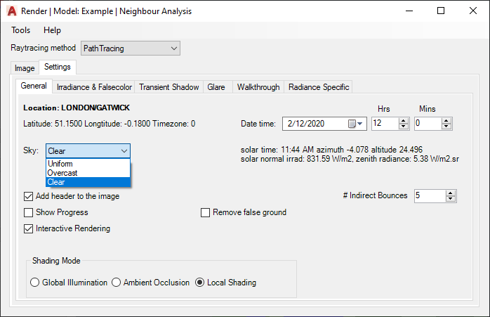
Shading Modes
There are three Shading mode supported in Path tracing mode:
- Global Illumination which produces unbiased path-traced simulation of light paths. This is the default mode.
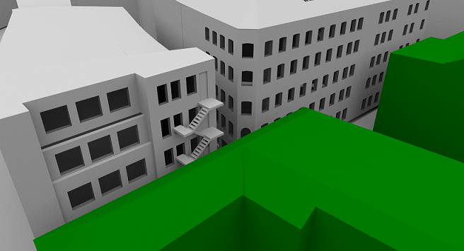
- Ambient Occlusion option accounts only for the visiblity term. A cosine-weighted visibility factor calculated for the hemisphere of a surface point. An example is demonstrated here.
- Local Shading mode quicken the rendering but removing diffuse inter-reflection from calculation. Phong-shading model is used to render materials with pre-defined three directional lights.

Irradiance and Sky Component image
The process is same as described for rendering normal images. The maximum range of legend colours is set in Render dialog Options > Irradiance and Falsecolor tab.
The minimum is always set to zero. The maximum value can be set and is interpreted as follow:
- Values between 0 to 100 is used as Daylight Factor or Sky Component ratio.
- Values above 100 are taken as absolute lux value.
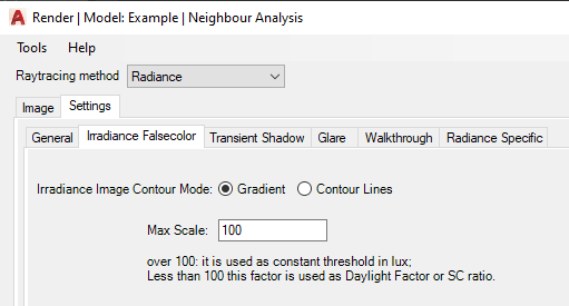
If Radiance is selected as the rendering method, two false color image modes are provided:
– Gradient option produces smooth interpolation between values on the image.
– If contour lines are desired rather than just false color image, the Contour Lines option can be used. These lines are placed over the normal Radiance picture rather than falsecolor image.
– Contour Bands produces contour bands instead of lines, where the thickness of the bands is related to the rate of change in the image.
Note:
Radiance falsecolor image uses pre-defined Radiance pm3d colour palette with 8 colours.
The image on the side shows daylight factor gradient image with corresponding values set in legend, for an indoor scene.
An hdr file format is saved along the png format, loaded through Tools > Load hdr image, which can be used to display the image with different legend colours without re-rendering the image.